- [블로그] 전자과 공대생 블로그(전자회로)
- [블로그] 전자과 공대생(전자기학)
- [블로그] 배고픈 대학원생 (RF 아날로그)
- [블로그] 나라발전 교수님 (아날로그)
- [블로그] 전자과 숩달씨 ( 아날로그 회로 Razavi…
- [VOD] IDEC 아날로그회로 - 고형호 교수님 (충…
- [VOD] IDEC 아날로그회로2
- [VOD] IDEC 아날로그회로3 - 이강윤 교수님(성…
- [VOD] IDEC 아날로그회로 직관적해석 - 심재윤 …
- [VOD] IDEC 아날로그 LNA - 고형호 교수님 …
- [VOD] IDEC 아날로그집적회로 실습
- [VOD] Cadence OPAMP Verificati…
- [VOD] IDEC Full-Custom Flow 교육…
- [VOD] IDEC RF System-유형준 교수님(K…
- [VOD] IDEC 디지털 Cell-based 설계
- [VOD] IDEC PLL
- [VOD] IDEC CentOS 7 (Linux)
- [VOD] Band Gap Reference 정리
- [강의] 회로설계 멘토 삼코치
- [강의] OpAmp > CMFB
- [강의] 변박사님 : OpAmp, Radar
- [강의] PMIC - 박병하 교수님 (유료)
- [강의] 삼코치 -아날로그 회설 직무 (유료)
합법적사기꾼지망생
전자회로1_03 : MOSFET 정리 PDF + 공식*** 본문
0. MOSFET의 구조 및 Symbol(심볼) (E-mode vs. D-mode)


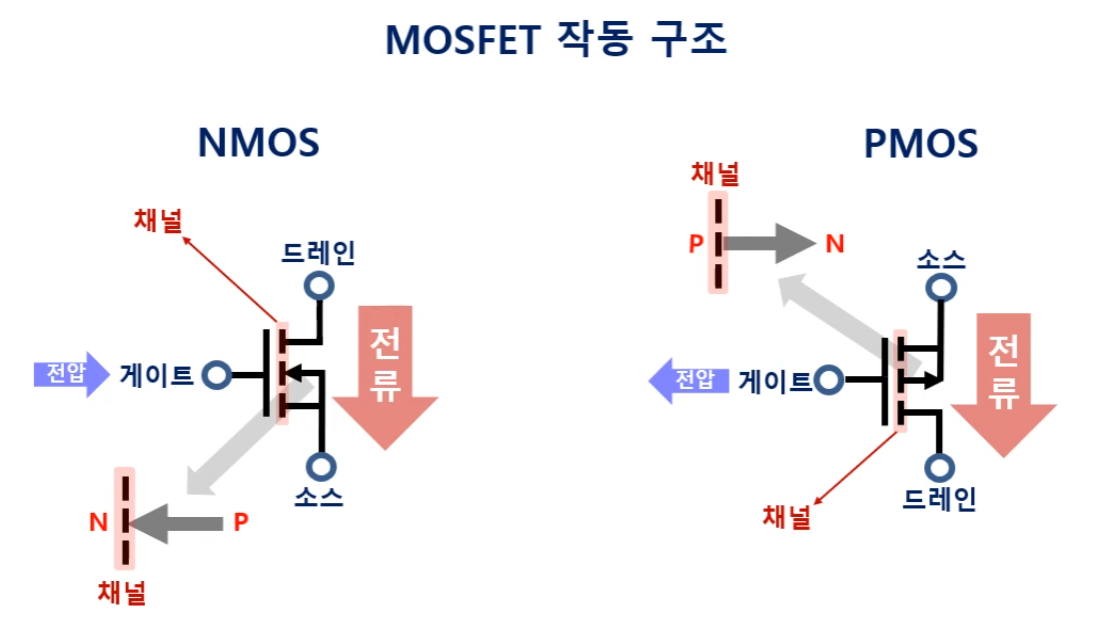
0-1. 트랜지스터의 종류


1. 동작 모드 : Triode Mode vs. Saturation Mode

(1) Triode

(2) Saturation

1-1. 동작원리

2. Transconductance of Saturation Mode


3. Saturation Region with Channel Length Modulation


4. Output Impedance of Saturation Mode (Channel Length Modulation)
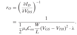

※ Intrinsic Gain
Load가 open일 때(혹은 ideal current source = small signal open) (병렬 연산이므로 ro만 남음), MOSFET으로 이뤄진 CS amplifier의 voltage gain을 의미


5. Deep Tiode Mode + on-resistance


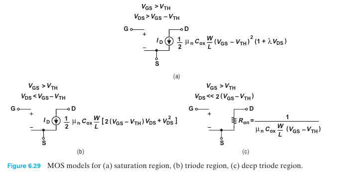
6. Saturation Current Mode


7. Body Effect

8. PMOS
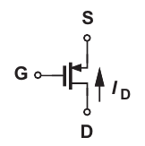
(1) 대소 관계 및 부호
V_Source > V_Gate > V_Drain
I_D < 0, I_S >0
V_GS < 0, V_DS < 0, Vthp < 0
lambda_p > 0
(2) I-V 관계식

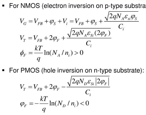
※ threhold voltage 유도 공식(반도체 공학)
9. Temperature에 따른 Drain Current
- Temp 증가 -> Thermal Voltage(VT) 감소 (Vt= kT/q) -> Threshold Votage (Vth) 감소 -> ID 증가 (제곱에 비례)
- Temp 증가 -> mobility 감소 -> Kn' 감소 -> ID 감소 (비례)
- 결론 : ID 증가 (하지만 일정 온도 이상부터는 mobility가 심하게 감소하여 ID 감소)
- 온도가 상승하면 문턱전압이 낮아짐.
- 온도가 상승하면 ID증가하다가 감소
- 온도가 상승하면 누설전류가 기하급수적으로 증가.
참조)
[전자소자] 현대 반도체 소자 공학 - Vel.. : 네이버블로그 (naver.com)
경기짱구의 여행 : 네이버 블로그
.
blog.naver.com
MOSFET(3) - 문턱전압, 포화전류, 누.. : 네이버블로그
MOSFET(3) - 문턱전압, 포화전류, 누설전류, Sub-Threshold, GIDL, 온도특성
안녕하세요~ 오늘은 MOSFET의 마지막 포스팅이 되겠네요. 마지막까지 화이팅~! - MOSFET의 전...
blog.naver.com
[전자회로공학2]week6. (Intrinsic gain~ IC 칩에서 Current Source, Amp 해석) :: 학부연구생의 공부일지
[전자회로공학2]week6. (Intrinsic gain~ IC 칩에서 Current Source, Amp 해석)
1. Basic Gain cell - Rd가 없는 current source 2. Intrinsic Gain 3. Ideal - > Practical Amplifer의 Current Source Voltage Transfer Characteristic 4. Increasing the gain of the Basic Cell
cvlab.tistory.com
amplifier - Intrinsic gain of NMOS - Electrical Engineering Stack Exchange
Intrinsic gain of NMOS
In Razabi's Design of Analog CMOS Integrated Circuits textbook, the example 3.2 asks for the small signal voltage gain of the circuit below: He explains that since the current source I1 introduces...
electronics.stackexchange.com
'A1_전기회로 & 전자회로 > 전자회로1' 카테고리의 다른 글
| 전자회로 정리 사이트(강의자료(Berkeley), 블로그) (0) | 2024.02.12 |
|---|---|
| 전자회로1_02 : BJT 정리 PDF (0) | 2022.10.31 |
| 전자회로1_01 : Diode 정리 (0) | 2022.10.31 |
| 전자회로1_05 : Current Mirror 정리 PDF (0) | 2022.10.29 |
| 전자회로1_04 : Amp 설명 및 총정리 (~cascode)*** (0) | 2022.10.28 |
